


Torque Based Engine Management System:
These represent new method in the control unit world today. Now, instead we are going to analyze the main strategy for the control of turbo-petrol engines. This strategy is based on the control and monitoring of the engine torque. The torque based control strategy arrows From the need to have more efficient and responsive engines, we are always checking their missions. This strategy directly manages engine performance by controlling air, fuel and spark advance. We have seen that no matter how accurate the MAF and MAP sensors or the MICRO-CONTROLLER doing the calculations are. The previous strategies do not have the ability to determine what is really going on in the engine in terms of performance. In addition, automotive groups have an increasing need to certify that the emissions produced by the performance are identical for all the mass-produced cars. Therefore, it became necessary to introduce a new parameter on which to base the entire control strategy, they would make it possible to represent engine performance by managing fuel and ignition advance to air regulation. ECU developers have identified all of these with engine torque. Let's take a look at features.
The torque of a rotating object is a specific case of the crankshaft is nothing more than the result of this formula where:

T is the Engine Torque in Newton Meter.
F is the Force applied to the shaft which determines its rotational acceleration in Newton.
A is the distance between the center of the shaft and the crank on which the Force ‘’F’’ is applied in Meter. By definition,
 =S/2
=S/2
 is half of the piston stroke ‘’S’’.
The force “F” applied to the shaft can be determined thanks to some characteristics of the engine. Such as:

p= the thrust pressure present in the cylinder in the expansion phase caused by combustion and
Ap= the cylinder head area measured in square meter.
In turn, the cylinder head area can be calculated with this formula:
Ap= 
B= represents the diameter of the piston head, called a bore expressed in Meters.
At this point, if we calculate the cylinder head area in the Force formula, we get this result.

Going back to the generic torque formula and replacing the force applied to the shaft with the formula just obtained, the shaft torque is determined:

Where , as we said at the beginning is the half stroke of the piston.
The later formula calculates the volume of the cylinder “displaced” during the stroke of the piston.


Vd=Volume of cylinder “displaced” during the stroke of Piston
For this, we can summarize the entire formula of the torque applied to the shaft.
Up until now, we have considered the instantaneous cylinder pressure.

At the that point, the formula is used only in the latest generation engines. For the other engines, a theoretical substitute is used. It is considered the actual medium pressure:
Pme: actual medium pressure theoretical [psi]
During a complete combustion cycle formed by two rotations of the shaft for a four stroke engine. This data is provided for each engine in the manufacturer's datasheets. By replacing the instantaneous cylinder pressure “P” with the actual medium pressure “ ” expressed in
  , we obtain the torque where,

2 times  represents a complete rotation =
1.  is a constant numerical factor that represents the number of rotations of the crankshaft for each combustion cycle. For a four stroke engine, it’s 2. While for a two stroke engine, it’s 1.
Knowing the pressure, the volume, the constant of the type of engine (two or four strokes) and the diameter, the engine torque can be easily calculated even without specific sensors or measuring equipment.
Little Known Fact:
ECU manufacturers wanting to develop a new engine control strategy, could have relied entirely on the power developed. However, the choice of using the torque applied to the shaft was preferred. The calculation of power is based on a measurement determined by a complex series of sensors, Rather Than on technical engine or torque parameters.
This is because the sensors can deteriorate overtime and alter the calculations of the ECU. The torque is also preferable because it allows an exchange of data between the ECU and the control units of the other modules connected to the vehicle’s internal network (CAN Network) es. gearbox, body-computer and etc.
The devices connected to the OBD ll diagnostic socket.
The vehicle stability and traction control systems like ESP, ASR, ABS, etc.
Now Let’s Try and Understand How The ECU Uses Torque Based Control Strategy?
In this case as well, the three factors that determine combustion are:
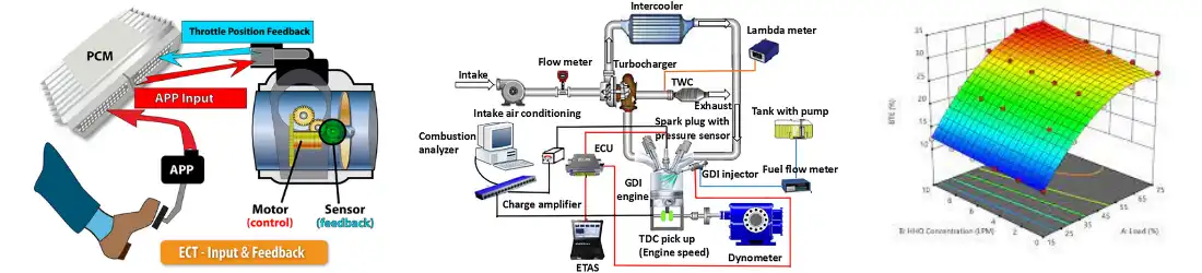
- Air, in particular only the fraction of fresh air charge entering the intake duct, without counting the amount of exhaust gas, recirculated by the EGR valve. The lambda carburation value defined by the various carburation maps present in the original ECU file. In the event of “closed-loop” operating strategy, the lambda value will be customly corrected to keep the carburation at “1”.
- The ignition timing valve, previously defined by the engine control unit. The torque based control strategy uses a closed-loop mechanism similar to the mass flow metering and speed density strategy, but in addition to measuring the actual carburation after combustion, it also considers the spark advanced value upstream. Therefore, carburation and ignition play a primary role in determining the engine torque. Let’s see how Using these data points:
The ECU uses the indicated “mean effective torque” link to the work of the piston as reference, indicated as  .
.
It serves to convert the gas pressure generated during an expensive phase inside the cylinder pressure into the force applied to the shaft. This is a theoretical value. It is not considered friction, pumping, inertia forces and torque losses necessary to move auxiliary components.
For example: the ECU will have to store the data as single maps that contain negative torque values that represent lost torque values. These maps contain experimental data and are generated by the engineers during the various functional tests of the engine placed on an engine test bench. Usually, the mean effective torque is also replaced by the course by the value tested during the development of the engine.
The Internal Calculated Torque:
As we have already mentioned, excludes friction or forces of any kind instead the torque loss is always a negative number. Since it represents lost torque values, measured during the various functional tests. It is important to take the lost torque into account as this will reduce the torque available to the wheels and will consequently decrease the performance of the vehicle. To give an example: the maximum engine torque developed by an engine with a 2.0 liter displacement, at 2400 RPM is approximately 300 N.m. but the lost torque is approximately 41 N.m. Therefore, the torque discharged to the ground will be equal to the difference between the maximum engine torque and lost torque:
 =
=  -
- 
Te = Engine Torque
Tinc = Internal Calculated Torque
Tpump= the loss due to the gas exchange and the pumping effect necessary to bring the air inside the cylinder in the intake phase
By convention, the engine torque (Te) is the result of the difference between “  “ and “
 ”. So, the formula we saw previously ( T = p
 ), is the one used by the manufacturer when designing the engine. While this is used internally by the ECU with the torque data preset by the manufacturer.
Before getting to the wheels, we find the torque to the clutch  :
:
= - 
TC= Torque to the clutch
Te= engine Torque
Tfri= the losses due to the various frictions of the peripheral components connected with chains or belts to the crankshaft
This value is the result of the difference between the engine torque “” and “”:
The other losses are related to the gearbox used, transmission axis and the differential of the drive wheels. Data relating to component losses are verified, by using a roller bench by the calibrators when the engine is installed in the vehicle.
Let’s take a look at the formula for the final calculation where:
 =
= 


= the actual average braking power. Estimated thanks to the loss of torque and corrected by the multipliers related to the carburation and ignition advance efficiency expressed in  .
.
is the multiplier relating to the carburation efficiency  .
.
is the multiplier relating to the efficiency of the engine spark advance.
BOSCH, like other ECU manufacturer’s, uses a procedure that follows this logic. In some similar ways to the previous procedure presented.
The internally calculated torque is represented on a map stored in the original file. It depends on two variables; Engine revolutions and the loads.
These torque values are measured during calibration by keeping the object of carburation at the stoichiometric value.
Lambda = 1
Or
Air/Fuel Ratio = 14.7 and spark advance values relating to the “optimal engine spark advance” map .
They are developed for achieving maximum inner torque.
The real meaning of the “” is the carburation efficiency. It is slightly different for each type of engine design, but as a similar form to the one shown in this graphic.
Here, it is evident that the maximum efficiency is 1. The value is found when the carburation detected by the lambda probe and the exhaust measures 0.9 lambda. Very Often, you can find this value in the map called “Desired Lambda” used during the open-loop operating strategy. The efficiency of the spark advance relative to the “” depends on the difference calculated between the spark advance value taken from the “optimal engine spark advance” map and that present in the “base spark advance” map with the same engine revolution’s and load’s.
 =
=  -
- 
= Efficiency of the spark advance relative.
= Spark advance value taken from the “optimal engine spark advance” map.
= Present in the “base spark advance” map.
The value of their difference is also called “ ”. Maximum efficiency is achieved when the result of the optimal and base engine spark advance maps are equal. That is, when their difference is zero.
= -  0 = 30 - 30
🏁In BOSCH control units, the maps relating to the lost torque due to gas exchange and the pumping effect and to the lost torque due to the various friction of the brutal components, connected with chains or belts to the crankshaft, both depend on engine RPMs and LOADs.
Now, let’s move on to the graphs that represent the multiplying factors that can intervene to increase or decrease the internal calculated torque.
The first relates to spark advance, the second to carburation and the last is introduced by BOSCH as a factor to manage exclusively vehicle software. This last graph, mainly depends on the control of the amount of fuel in the cylinder. It can be used by the control unit software to create aggressively lower levels of internal torque reduction. In this way, it is clear how the torque control strategy maximizes combustion efficiency. But also limits performance by using multiplicative factors.
From a theoretical point of view, we can therefore affirm that if on the one hand, the torque based control strategy has allowed many experts and beginner engineers to navigate in the remapping world, on the other hand, it has allowed ECU developers to introduce more and more control maps and limiters. In addition, some engine torque maps have been associated with software monitoring strategies and malfunctions (DTC errors). This was an additional obstacle for chip tuners. Because the ways to bypass or disable monitoring are different. They are blocks or limitations imposed on the control unit manufacturer. But also according to the make or manufacturer of the vehicle. In fact they can be associated with some manufacturer specific aero codes. For this reason, we will analyze how to manage the maps related to torque monitoring as we tackle the practical cases.
After learning this practical application of torque based control strategy, extremely useful for juggling most of the control units currently in circulation, we have reached the end of this article. We analyzed the concept of torque from a generic point of view, and then applied it to the engine and clutch.
Lastly, we learned how the strategy was reworked by one of the main ECU manufacturer’s. To allow both the increase and the limitation of vehicle performance.
What is Torque Monitoring?
Torque monitoring is a system used in modern engine control units (ECUs) to ensure that the actual torque produced by the engine matches the driver’s request and stays within safe mechanical limits. It's a key part of torque based engine management systems, especially in turbocharged and drive-by-wire vehicles.
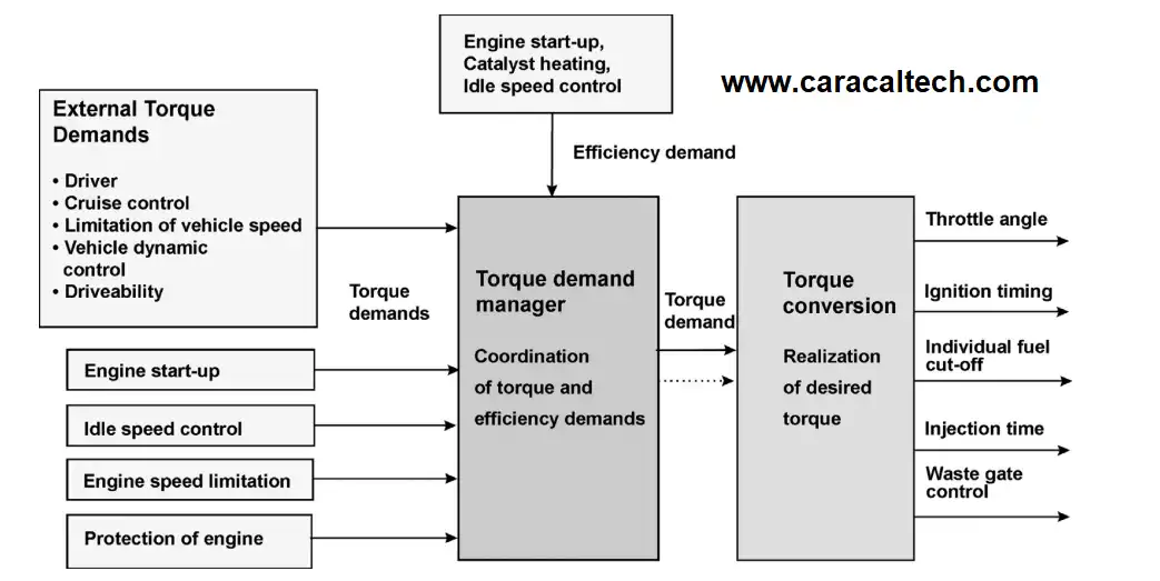
Torque monitoring involves real-time comparison of:
1) Requested Torque – What the ECU calculates based on inputs like throttle position, cruise control, or traction control.
2) Estimated Torque – What the engine is likely producing based on various sensor data (air mass, fuel, ignition timing, boost, etc.).
3) Delivered Torque – Sometimes derived from wheel torque or transmission models.
The ECU uses torque models to estimate output and checks for discrepancies that could indicate:
- Sensor malfunctions
- Mechanical faults
- Over-torque (risk to drivetrain or gearbox)
- Tuning that alters torque outside allowed boundaries
If these checks fail, the ECU can trigger torque monitoring faults, causing:
- Limp mode
- DTCs (Diagnostic Trouble Codes)
- Throttle cut or boost reduction
What Means Torque Monitoring Off?
Torque Monitoring Off usually refers to Disabling or bypassing torque monitoring logic in the ECU software. It often done during ECU tuning when:
- You've increased power significantly (e.g. bigger turbo, higher boost)
- Stock torque model is no longer accurate
- You’re running non-stock injectors or MAF less setups
Risks of Torque Monitoring Off:
Therefore, considering these risks, it is very important that this work be done by professionals.
- You remove safety nets that protect engine and drivetrain.
- Can cause gearbox or clutch damage if torque exceeds design limits.
- May interfere with traction/stability control and torque request logic.
- Can make it harder to diagnose real problems later.
When Torque monitoring off Done?
In stage 2/3+ ECU remaps
On platforms like Bosch ME7, MED17, MG1, etc.
Often paired with custom torque models or torque request limit changes
What is Torque to IQ conversion?
The Torque to IQ (Injection Quantity) conversion is a core function in torque based ECU architectures (especially on Bosch ECUs like EDC16/17, MED17, MG1, etc.).
In torque based systems, the ECU doesn’t just react to pedal input. It first calculates a torque request, then figures out how to achieve that torque by controlling boost, air, and finally fuel (injection quantity, or IQ).
The Torque to IQ converting is the final step in that chain:
"Given the requested torque, how much fuel (IQ) do I need to inject to produce it?"
How “Torque to IQ conversion” Works?
This is principle of Torque to IQ conversion:
1) Driver presses the pedal
2) ECU calculates Driver Requested Torque
3) ECU applies limits (traction control, clutch protection, torque limiters)
4) Resulting final torque request is passed to the Torque to IQ map
5) Map converts torque (Nm) to Injection Quantity (mg/stroke)
6) IQ is then used to control injectors (duration, timing, etc.)
Why Torque to IQ Matters in ECU Tuning?
If you increase torque (e.g. via boost), but don’t adjust the Torque to IQ map, the ECU might underfuel or overfuel. It’s crucial to scale this map when:
- You've increased torque output (e.g. turbo upgrade)
- You're changing injectors or fuel pressure
- You're modifying torque monitoring logic
Mismatch here can trigger torque monitoring faults, incorrect smoke control, or limp mode.
📍If you need DTC Off Service you can use our Tuning File Service.
📍For more information and probable problems feel free to contact us: support@caracaltech.com