


What is “Air Control System”?
Air control refers to tables related to controlling the air entering to the engine. Air control tables are tables, whose task is to control the engine’s air entering. This means how much air passes through the throttle and enters to the engine at different engine speed and load.
And also, this amount of air intake depends so many factors such as throttle operating angle, engine speed, pressure and temperature. ECU calculates and determines the amount of fuel and other parameters in proportion to air mass entering to the engine. Therefore, there are tables related to intake air control inside the ECU. Air control mainly includes tables of requested engine load, air mass through throttle valve, and throttle valve operating angle.
That we teach all of these tables completely and step by step.
What is “Air Control System”?
In an internal combustion engine, the throttle is a means of controlling the engine's power by regulating the amount of fuel or air entering the engine. In a motor vehicle, the control used by the driver to regulate power is sometimes called the throttle, accelerator, or gas pedal. For a petrol engine, the throttle most commonly regulates the amount of air and fuel allowed to enter the engine.
In fuel-injected engines, the throttle body is the part of the air intake system that controls the amount of air flowing into the engine in response to driver accelerator pedal input primarily. The throttle body is usually located between the air filter box and the intake manifold, and it is usually attached to or near the MAF sensor.
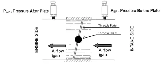
The largest piece inside the throttle body is the throttle plate, which is a butterfly valve that regulates the airflow. On many cars, the accelerator pedal motion is communicated via the throttle cable, which is mechanically connected to the throttle linkages that, in turn, rotate the throttle plate. In cars with electronic throttle control, also known as "drive-by-wire", an electric actuator controls the throttle linkages, and the accelerator pedal connects not to the throttle body but to a sensor that outputs a signal proportional to the current pedal position and sends it to the ECU. The ECU then determines the throttle operating based on the accelerator pedal's position and inputs from other engine sensors such as the engine coolant temperature sensor.
What is Throttle Body System?
Air control refers to tables related to controlling the air entering the engine. Air control tables are responsible for controlling the amount of air entering the engine, which depends on various factors such as throttle operating angle, engine speed, pressure, and temperature. The ECU calculates and determines the amount of fuel and other parameters proportional to the air mass entering the engine. Therefore, there are tables related to intake air control inside the ECU. Air control mainly includes tables of requested engine load, air mass through the throttle valve, and throttle valve operating angle. We will teach all of these tables completely and step by step.
When the driver presses down on the accelerator pedal, the throttle plate undergoes rotation inside the throttle body, thereby opening up the throttle passage and allowing for an influx of air into the intake manifold. The vacuum present in the manifold immediately draws in the air. Typically, a mass airflow sensor gauges this change and transmits the information to the Engine Control Unit or ECU. Subsequently, the ECU augments the amount of fuel injected by the injectors to achieve the desired Air/Fuel ratio. A throttle position sensor (TPS) is usually affixed to the throttle plate's shaft to furnish the ECU with pertinent data concerning the throttle's current position- whether it is at idle, wide-open throttle (WOT), or somewhere in between these two extremes.
Contemporary engines are frequently equipped with drive-by-wire systems, in which sensors track the driver's controls and a computerized system regulates the flow of fuel and air. This means that the operator does not exercise direct control over the fuel and air supply.
The electronic control unit (ECU) can achieve superior management of these systems in order to reduce emissions, optimize performance, and adjust the engine idle to expedite warming up or compensate for added engine loads such as running air conditioning compressors, thereby averting engine stalls.
In summary, a throttle body serves as a butterfly valve situated between the air intake filter and the intake manifold. It governs the amount of air passing into the engine based on the driver's input through the gas pedal. As the air inflow increases, more fuel is injected, resulting in greater power output. In modern times, throttle bodies are predominantly electronically regulated, whereas this particular throttle body is mechanical. It includes provisions for the throttle position sensor (TPS) and manifold absolute pressure (MAP) sensor inputs, as well as routing for the idle air control (IAC) valve and idle adjustment screw.
Air mass flow is the amount of air that flows through a throttle body, typically measured in grams/second (g/s) or Kilograms per hour. By measuring the size and area of the throttle body, as well as pre and post throttle pressures and temperature, the Engine Control Unit (ECU) can accurately calculate air flow into the engine. This calculation is known as the Throttle Mass Flow (TMF) Calculation. Additionally, other sensors such as manifold pressure and mass air flow sensors can also provide air mass flow data.
The TMF Calculation method offers several advantages over MAP and MAF methods, which will be discussed later on. However, critical parameters to consider when calculating air flow mass include pressure before the throttle plate, pressure after the throttle plate, temperature, throttle operating angle, and engine speed.
But what do we mean by "Pressure source before and after the throttle plate"?
In forced induction engines, boost pressure (or charge pressure) is used as the Pre-Throttle pressure source. In naturally aspirated engines, barometric pressure serves as the Pre-Throttle pressure source, while manifold pressure is used as the source after the throttle plate.
Throttle Pressure Ratio is defined as the ratio of intake manifold pressure to the pressure upstream of the throttle valve limit.
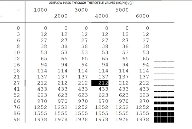
This table represents the mathematical model of air flow mass passing through the throttle valve. The model considers the operating percentage, engine speed, and intake manifold pressure divided by pressure upstream of throttle valve limit, depending on the Bosch ME generation of ECU.
For Bosch ME7, the horizontal axis is engine speed, while for Bosch ME9 and later generations, it is intake manifold pressure divided by pressure upstream of throttle valve limit. The vertical axis shows the throttle valve operating angle.
By using this table, the ECU can detect the amount of intake air. The Y-axis represents the percentage of throttle operation, and the X-axis is either the engine revolution or pressure ratio, depending on the ECU generation. The numbers in the table indicate air flow mass in kilograms per hour that passes through the throttle valve.
The table is used to determine airflow based on throttle position, pressure ratio, or engine speed. It allows for comparison with the invert map of throttle valve operating, thus functioning as a feedback system.
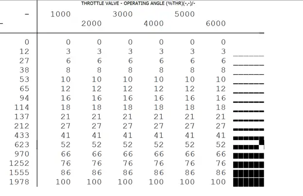
This table shows the mathematical model of throttle valve operating angle based on air flow mass and intake manifold pressure divided by pressure upstream of throttle valve limit.
For Bosch ME7 ECU generation, the horizontal axis is engine speed, while for Bosch ME9 and later generations, the horizontal axis is intake manifold pressure divided by pressure upstream of throttle valve limit. The Y-axis represents air flow mass that passes through the throttle valve in kilograms per hour. The X-axis indicates the engine speed or pressure ratio, and the numbers in the table show the percentage of throttle valve operating angle.
In a car with electronic throttle valves, this table follows different rules depending on the mode of operation.
In self-starter mode, the valve opens slightly at start-up to allow air to enter the engine, helping it start quickly.
In idle mode, the electric throttle adjusts the idle revolution when the car turns on and runs at idle, changing as the angle increases or decreases.
When the car is in motion, the ECU commands the throttle to open in proportion to the accelerator pedal pressed by the driver.
Additionally, this table helps prevent the engine revolution from falling when setting the air conditioner, turning the steering wheel, or when the gearbox is in gear D or other gears.
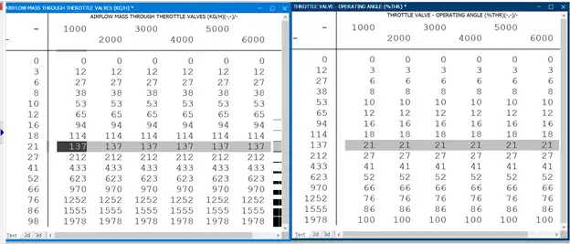
The pictures provided depict the correlation between the angle of the throttle valve and the mass of airflow through it. The Engine Control Unit (ECU) utilizes both tables to regulate and compute the air mass and throttle operation. It is essential to note that the throttle valve operating angle is the reciprocal of the air mass flowing through the throttle valve.
In simpler terms, an angle of 21% on the throttle indicates that 137 kilograms of air are passing through it. Similarly, when 137 kilograms of air pass through the throttle, the angle measures 21%. It becomes necessary to tune both maps when replacing the original turbocharger or upgrading the intake duct to accommodate a larger throttle body. Mechanical tuning significantly affects modifications made to these two tables, and bigger throttle body sizes impact calculations.
To coordinate 100% throttle before attaining the "full load condition," you can typically adjust the last row of the "Throttle valve operating angle" map. It is crucial to remember the difference in the horizontal axis, which is usually RPM for Bosch ME7. However, in later generations such as ME9, the horizontal axis reflects the intake manifold pressure divided by the limit of pressure upstream of the throttle valve.
📍For more information and probable problems feel free to contact us: support@caracaltech.com